

Description
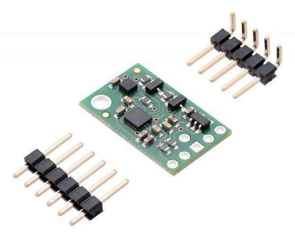
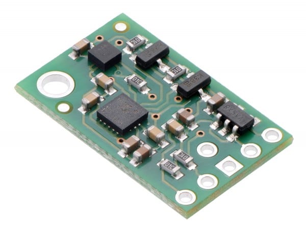
The Pololu MinIMU-9 v5 is a compact (0.8? × 0.5?) board that combines ST?s LSM6DS33 3-axis gyroscope and 3-axis accelerometer and LIS3MDL 3-axis magnetometer to form an inertial measurement unit (IMU); we therefore recommend careful reading of the LSM6DS33 datasheet (1MB pdf) and LIS3MDL datasheet (2MB pdf) before using this product. These sensors are great ICs, but their small packages make them difficult for the typical student or hobbyist to use. They also operate at voltages below 3.6 V, which can make interfacing difficult for microcontrollers operating at 5 V. The MinIMU-9 v5 addresses these issues by incorporating additional electronics, including a voltage regulator and a level-shifting circuit, while keeping the overall size as compact as possible. The board ships fully populated with its SMD components, including the LSM6DS33 and LIS3MDL, as shown in the product picture.
Compared to the previous MinIMU-9 v3, the v5 version uses newer MEMS sensors that provide some increases in accuracy (lower noise and zero-rate offsets). The MinIMU-9 v5 is pin-compatible with the MinIMU-9 v3, but because it uses different sensor chips, software written for older IMU versions will need to be changed to work with the v5.
The MinIMU-9 v5 is also pin-compatible with the AltIMU-10 v5, which offers the same functionality augmented by a digital barometer that can be used to obtain pressure and altitude measurements. The AltIMU includes a second mounting hole and is 0.2? longer than the MinIMU. Any code written for the MinIMU-9 v5 should also work with the AltIMU-10 v5.
  |
| Side-by-side comparison of the MinIMU-9 v5 with the AltIMU-10 v5. |
|---|
The LSM6DS33 and LIS3MDL have many configurable options, including dynamically selectable sensitivities for the gyro, accelerometer, and magnetometer. Each sensor also has a choice of output data rates. The two ICs can be accessed through a shared I²C/TWI interface, allowing the sensors to be addressed individually via a single clock line and a single data line. Additionally, a slave address configuration pin allows users to change the sensors? I²C addresses and have two MinIMUs connected on the same I²C bus. (For additional information, see the I²C Communication section below.)
The nine independent rotation, acceleration, and magnetic readings (sometimes called 9DOF) provide all the data needed to make an attitude and heading reference system (AHRS). With an appropriate algorithm, a microcontroller or computer can use the data to calculate the orientation of the MinIMU board. The gyro can be used to very accurately track rotation on a short timescale, while the accelerometer and compass can help compensate for gyro drift over time by providing an absolute frame of reference. The respective axes of the two chips are aligned on the board to facilitate these sensor fusion calculations.
The carrier board includes a low-dropout linear voltage regulator that provides the 3.3 V required by the LSM6DS33 and LIS3MDL, allowing the module to be powered from a single 2.5 V to 5.5 V supply. The regulator output is available on the VDD pin and can supply almost 150 mA to external devices. The breakout board also includes a circuit that shifts the I²C clock and data lines to the same logic voltage level as the supplied VIN, making it simple to interface the board with 5 V systems. The board?s 0.1? pin spacing makes it easy to use with standard solderless breadboards and 0.1? perfboards.
Specifications
- Dimensions: 0.8? × 0.5? × 0.1? (20 mm × 13 mm × 3 mm)
- Weight without header pins: 0.7 g (0.02 oz)
- Operating voltage: 2.5 V to 5.5 V
- Supply current: 5 mA
- Output format (I²C):
- Gyro: one 16-bit reading per axis
- Accelerometer: one 16-bit reading per axis
- Magnetometer: one 16-bit reading per axis
- Sensitivity range:
- Gyro: ±125, ±245, ±500, ±1000, or ±2000°/s
- Accelerometer: ±2, ±4, ±8, or ±16 g
- Magnetometer: ±4, ±8, ±12, or ±16 gauss
Included Components
A 1×6 strip of 0.1? header pins and a 1×5 strip of 0.1? right-angle header pins are included, as shown in the picture below. You can solder the header strip of your choice to the board for use with custom cables or solderless breadboards or solder wires directly to the board itself for more compact installations. The board features two mounting holes that work with #2 or M2 screws (not included).
 |
Encrypted payment
Your payment information is processed securely. We do not store credit card details nor have access to your credit card information.
Customs Tariff Number:
Country of origin:
This depends on where you are located. After the order is handed over to UPS, the delivery time in Germany is about 2-3 days, within Europe about 1 week.
We ship our orders with UPS (United Parcel Service).
If we still haven't answered your question, you can contact us below and we will get back to you as soon as possible.
